
Generating code from SysML V2 textual models#
 SysML® v2 is a newer version of SysML that is more flexible and powerful than v1. It now allows you to write textual models.
This lowers the barrier to model-based systems engineering (MBSE) considerably,
because no special (and often expensive) tools are needed. A lightweight entry into MBSE is possible. For example, a Visual Studio Code plugin is enought for the start (see below).
SysML® v2 is a newer version of SysML that is more flexible and powerful than v1. It now allows you to write textual models.
This lowers the barrier to model-based systems engineering (MBSE) considerably,
because no special (and often expensive) tools are needed. A lightweight entry into MBSE is possible. For example, a Visual Studio Code plugin is enought for the start (see below).
The Sinelabore Code Generator generates C++ and Python code as well as SVG model visualizations from SysML v2 textual models. Model text, executable code and the visualizations are therefore always in sync!
In opposite to the existing Sinelabore UML backends, now in addtion to state machines also structural code is generated.
Call the code generator with the parser flag -p Sysml2Text.
What comes out follows from -l: cppx for C++, python for Python, and
svg to draw the model instead of generating from it.
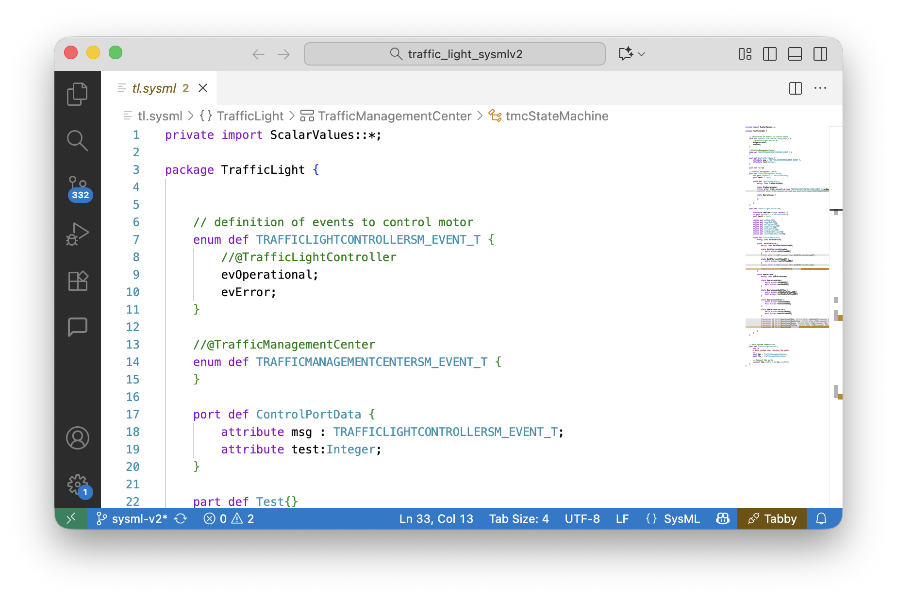
The SysML v2 code generation focuses on features needed to execute models: state machines, parts, ports and connections between parts and action behavior. For hints how to structure models for simulation and testing see our Modeling Guide.
To execute the generated code a small runtime environment is provided — framework.h
for C++, framework.py for Python. It contains some base classes and implements
inter-part communication via ports and timeout handling — the minimum needed to run a
model. Both are delivered with the product; neither is generated.
This ensures fast roundtrip times, allows to quickly generate mock-ups and simulations of an intended system.
Minimum language versions to compile or run the generated code:
- C++17 for
-l cppx— compile with-std=c++17or later. The runtime usesstd::variantandstd::visit, so C++14 is not enough.- Python 3.10 for
-l python. The runtime uses@dataclass(slots=True), which Python 3.9 and older reject.
For more details on the supported features, see the menu tree on the left. Where it is helpful text references are made to: OMG Systems Modeling Language™ (SysML®), Version 2.0 Part 1: Language Specification. OMG Document Number: formal/2026-03-02 Date: March 2026, Standard document URL: https://www.omg.org/spec/SysML/2.0/
Example#
The following listing shows an example for a small traffic light control system model. It consists of three parts with some attributes and actions. The TrafficManagementCenter part represents a central control unit that controls TrafficLightController parts connected via ports.
private import ScalarValues::*;

package TrafficLight {

    // definition of events for the traffic light controller
    enum def TLCEvent {
        evOperational;
        evError;
    }

    // the payload carried by the port
    item def ControlPortData {
        attribute msg : TLCEvent;
    }

    port def ControlPort {
        in item data : ControlPortData;
    }

    // traffic management center
    part def TrafficManagementCenter{
        out port sendPort : ControlPort;

        state tmcStateMachine {
            entry; then PreOperational;

            state PreOperational;
            accept after 2[SI::second] do send TLCEvent::evOperational via sendPort then Operational;

            state Operational;
        }
    }

    part def TrafficLightController{

        attribute msg : TLCEvent;
        in port recvPort : ~ControlPort;

        // the lamps this controller drives; wired from outside
        ref part redLamp : Lamp;
        ref part yellowLamp : Lamp;

        // read the port into 'msg' so transitions can guard on it
        action getMsg {
            action accept m : ControlPortData via recvPort {
                assign msg := m.msg;
            }
        }

        // switch a lamp by performing an action that belongs to the lamp
        action setRed    { first start; then perform redLamp.setOn;     then done; }
        action setYellow { first start; then perform yellowLamp.setOn;  then done; }

        state tlcStateMachine {
            do action getMsg;
            ...
        }
    }

	// Main system composition
	part def TrafficLightSystem {
		doc /*
		* Main system that contains the parts
		*/

		// one control center ...
		part tmc : TrafficManagementCenter;
		// ... manages two traffic lights
		part tlc1 : BasicTrafficLightController;
		part tlc2 : BasicTrafficLightController;

		// Connect the parts via its ports
		connect tmc.controlPort to tlc1.recvPort;
		connect tmc.controlPort to tlc2.recvPort;
		connect tlc2.servicePort to tmc.servicePort;
		connect tlc1.servicePort to tmc.servicePort;
}
In this model the TrafficManagementCenter enables traffic light controllers to operate by sending a start event. The TrafficLightController then changes state from OutOfService to Operational and performs expected traffic light operations. The example is rich enough to show the available possibilities. The TrafficLightSystem part weaves together the TrafficManagementCenter and the TrafficLightController parts.
Visual Representation of a Model#
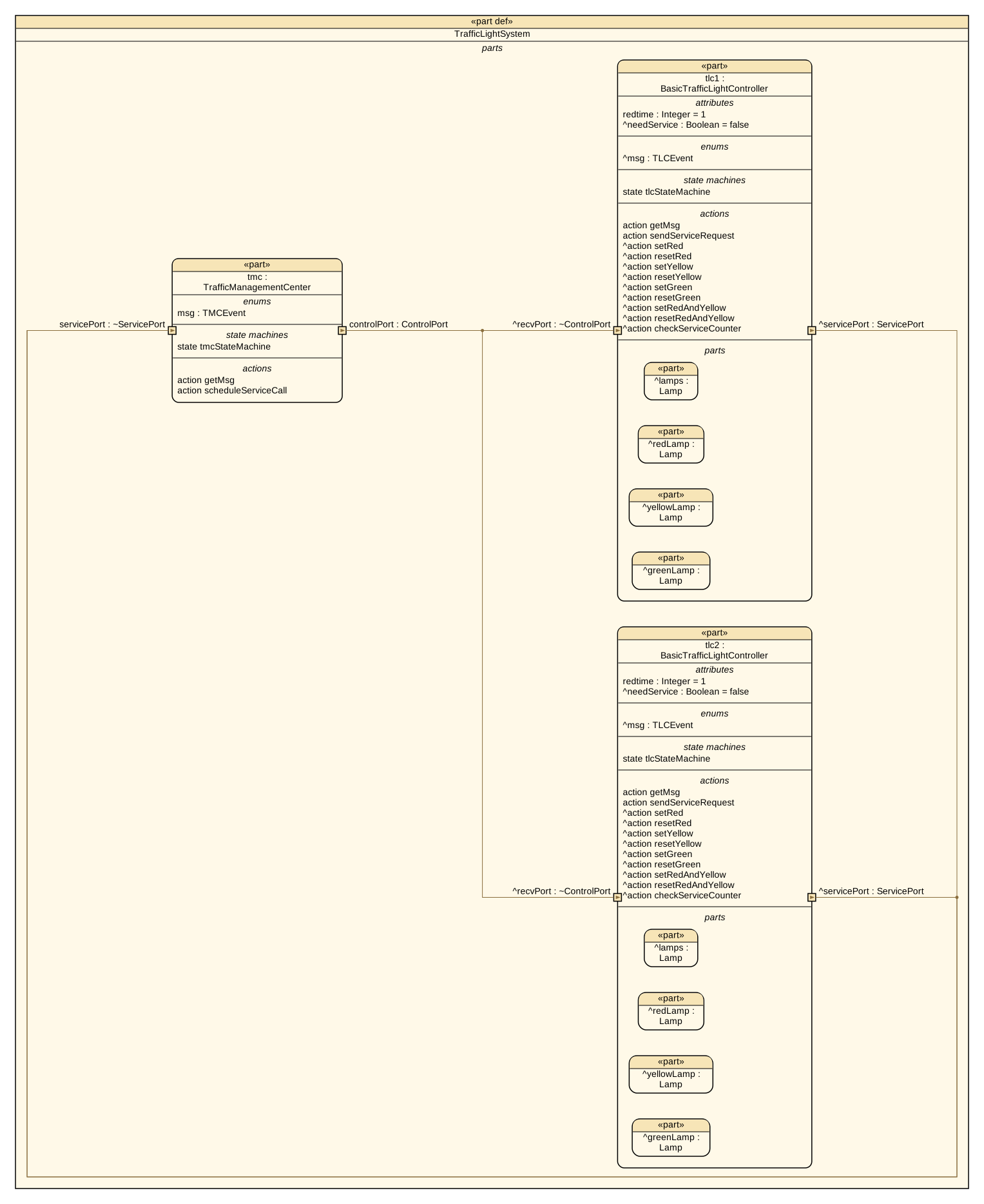
The next three figures shows differnt aspects of the model. All pictures were rendered from the very same model file, which is one of the practical benefits of a textual notation. The command that produced them is shown below; see also Tooling and Validation.
Use -l svg and name what to draw with -t. Three things can be drawn: the state machine of a part as a state chart, the flow of an action as an activity diagram, and the structure of a part with the parts it contains, their ports and what connects them.
A “part connection” drawing shows the parts a system is made of, the ports on their borders with the direction each one carries, and the connections between them, with a port name written along the connection it belongs to. How much a box carries beside its name is up to you: -pc chooses the compartments — attributes, enums, items, states, actions — and -pcd how far down the containment tree they are shown. It was drawn with -pcd 1, which is why the lamps inside each controller stay plain boxes.
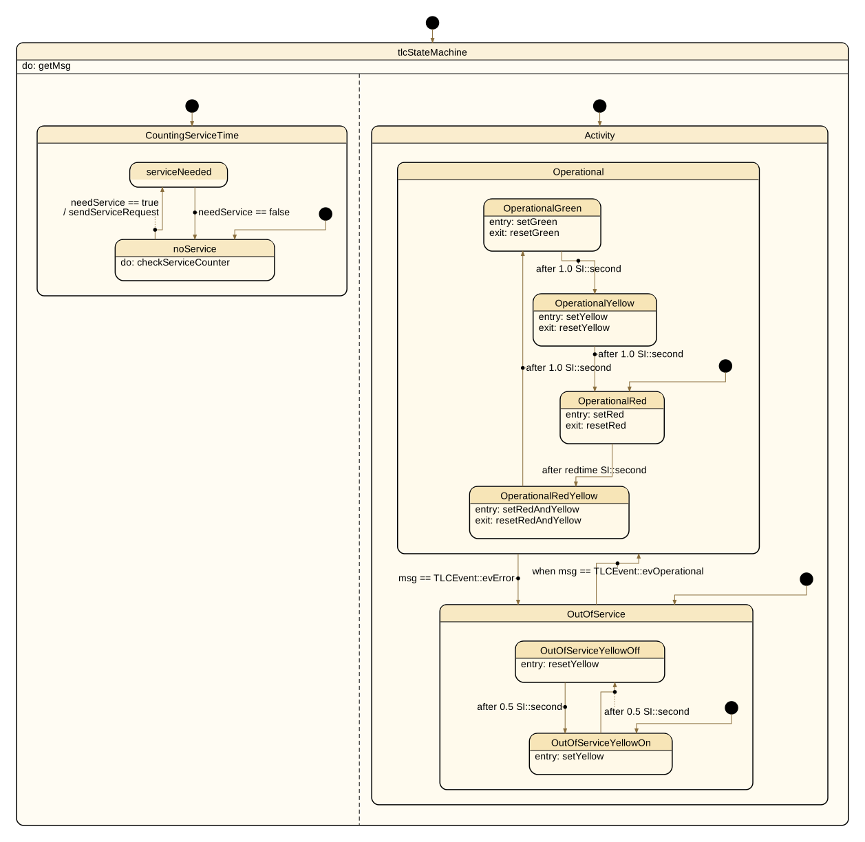
tlcStateMachine, drawn on BasicTrafficLightController: the two regions separated by the dashed line run in parallel, states nest, and each transition carries what it accepts and the guard it waits for — after redtime SI::second uses an attribute as its timeout, / sendServiceRequest is what the transition sends. What a state does is written inside it, as entry:, exit: and do:.
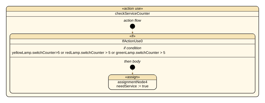
An action is drawn as its flow. checkServiceCounter is the action the state noService runs while it is active — the do: in the state chart above. Its body is one if over the three lamp counters and one assignment, and that is what the activity shows: the condition in full, and the assignment that runs when it holds.
action checkServiceCounter{
    first start;
    if yellowLamp.switchCounter > 5 or
        redLamp.switchCounter > 5 or
        greenLamp.switchCounter > 5
    {
        assign needService:=true;
    }
}
Here is how the pictures above were made:
java -cp "path/to/codegen/*" codegen.Main \
     -p sysml2text -l svg \
     -t TrafficLight::BasicTrafficLightController \
     -o tlcStateMachine tl.sysml signalling.sysml

java -cp "path/to/codegen/*" codegen.Main \
     -p sysml2text -l svg \
     -t action:TrafficLightController::checkServiceCounter \
     -o checkServiceCounter tl.sysml signalling.sysml

java -cp "path/to/codegen/*" codegen.Main \
     -p sysml2text -l svg -pcd 1 \
     -t TrafficLight::TrafficLightSystem \
     -o TrafficLightSystem tl.sysml signalling.sysml